Drag coefficients for i-beams pdf
the lowest drag coefficient value of .75 is still too high for a high performance sports car. Upon Upon completion, we expected to see drag coefficient values of between 0.3 and 0.5.
TwoParticle drag coefficients 3301different sets of axial coordinates of notable pointswere used: configuration 1: x0, xm1, xm2, xb, xt”6, 18.5,46, 60, 90 cm respectively configuration 2: x0, xm1, xm2, xb, xt”6, 11.0,54, 60, 90 cm, respectively.As shown in Fig. 3, the shaft occupied only a limitedportion of the full length of the external tube, thusleaving underneath a calming zone (30 cm long
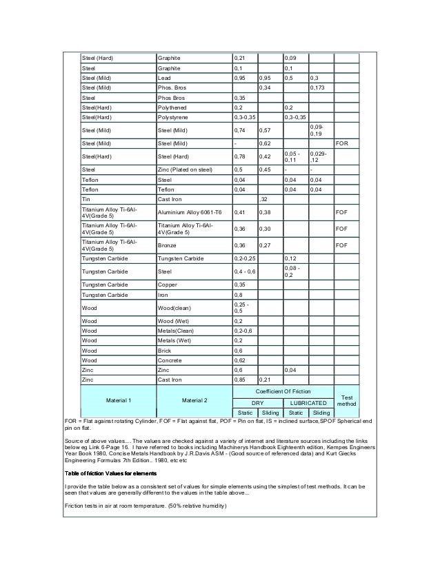
the examination into the friction coefficients for materials used in base-isolation and passive damping systems, the friction characteristics of conventional materials, say, steel versus steel, steel versus concrete, or wood
ACEPS – 2012 144 100N, the resolving power is 1/1000) were set at the upper and lower ends of each rod attached to the model, and the drag forces acting on …
122 Chapter 5 M3 System for Viscous Drag Reduction In aerospace engineering, drag reduction is one of the most challenging problems of aircraft. Drag limits the maximum speed, the maximum range of …
• the drag on a spherical particle in a fluid is described by Stokes’ Law for the following conditions: – fluid is a Newtonian incompressible fluid du k /dx k =0
Drag is the component of a force acting on a body that is projected along the direction of motion. Both shear forces and pressure induce drag on a body in motion.
Wind-induced tree sways SpringerLink

AERODYNAMIC FORCES ON AIRFOILS
Field measurements of drag coefficients for model large woody debris Bretagne Hygelunda, Michael Mangab,* aDepartment of Geological Sciences, University of Oregon, Eugene, OR 97403, USA
14-4 Induced Drag. For the given flight condition, the lift coefficient is CL (W/S)/q 0.21. Because of flow around the wing tips (see in the “drag-due-to-
1 bridge girder drag coefficients and wind-related bracing recommendations by zachary harper a thesis presented to the graduate school of the university of florida in partial fulfillment
Drag coefficient 1 Drag coefficient In fluid dynamics, the drag coefficient (commonly denoted as: cd, cx or cw) is a dimensionless quantity that is used to quantify the drag…
the drag coefficient is nearly constant or a slowly increasing function of wind speed (Large and Pond, 1980), and that it is a factor of two or three smaller than needed to …
5/05/2017 · I need to obtain drag coefficient calues for I-beams. I found a site stating it was 2.7, but it says nothing about the orientation?? I basically need the Cd-value for flow parallel to the I-beam, from the top and from the side.
Notes: Abstract: A key objective of this study was to experimentally quantify wind load coefficients (drag, torque, and lift) for common bridge girder shapes, and to quantify shielding effects arising from aerodynamic interference between adjacent girders.

The drag coefficients distribution was ascent or descent tendency according to the bed geometry, which showed that the bed length and the bed height were related closely to the flow characteristics.
Drag Coefficient(rev.3) Finally, the reader is strongly urged to buy him/her self a copy of Dr. Hoerner’s most wonderful book used as ref. 1 in this report.
The results obtained with type A beams are depicted in the left column of Figure 4, whereas those corresponding to porous H beams (type B) are shown in the right column of the same figure. Figure 4: Variation with the angle of attack, , of the lift coefficient, , the drag coefficient, , …
Particle drag coefficients in turbulent fluids [PDF
A wind load on a 100 ft structure with 50 lbs/ft on your beams will result in ridiculous overdesigns from the top to the bottom. I want to design every structure with as much complexity and time as possible, even if my boss gets mad b/c its taking to long!
The variation of horizontal drag coefficients, C D X and vertical drag coefficients, C D Y versus KC number is shown in Fig. 8 for aspect ratio = 1 2, for relative depth of submergence d / h = 4.68. The maximum value of KC obtained is about 2.25 and the value of β ranges from 26,860 to 56,537.
compute the drag coefficient (Eqs. 2 and 3). The general equation for the drag force on a section of tower for any arbitrary wind direction θ , with respect to the
GUIDELINES FOR TEMPORARY SHORING, Published October 25, 2004 5 5. TYPES OF TEMPORARY SHORING 1. A shoring box is a prefabricated shoring system which is installed as the excavation progresses. – a dream play pdf download drag coefficient is an important parameter for optimum design of single pole supports. With such an important role played by the drag coefficient, it is critical to know what factors influence the drag coefficient for single pole supports”. From previous studies, the drag coefficient has been shown to be affected by both the shape of the pole and the Reynolds number (Rr^.) . The Reynolds
An important parameter governing the drag coefficient of a body in free-molecule flow is the molecular speed ratio s defined by speed of satellite most probable molecular speecl The most probable molecular sieed vm at any altitude is given by T- , (3) where T is the
Measurements of drag at various angles of attack (0° to 40°) showed that with increase in turbulence level the minimum drag occurred at smaller values of angle of attack. Keywords: Octagonal cylinder, Drag coefficients, Lift coefficients, Tall building, Turbulent Stream
1. Purpose Some basic concepts of subsonic flow are demonstrated using a nominal 50 m/s wind tunnel. The section-lift and drag coefficients for a symmetric airfoil are obtained by analyzing the measured
coefficient, determining the static contact friction coefficient between the capsule and the pipe correctly, using a contraction coefficient some what larger than that for sharp- edged capsules, and using more accurate values of the capsule-to-pipe diameter ratio.
The drag coefficients in the three studied directions showed a reduction for turbulent flow. Further measurements were carried out for the model with an inclination of 80° relative to the flow
Introduction This NAR Research & Development report describes a series of experiments using a computerized wind tunnel to determine the drag coefficients of typical model rocket designs.
15/05/2003 · Table 2 is a summary of typical drag coefficients of streamlined bodies. Table 3 is a summary of drag data for airborne systems and road vehicles. Table 4 reports a summary of drag data for a human being performing some well known physical activities.
Pressure and Friction Drag II Hydromechanics VVR090 Drag and Lift – General Observations I Inconvenient to separate between pressure and frictional drag. Total drag force is taken to be the sum of : • drag in a two-dimensional flow (profile drag) • drag produced by end effects (induced drag) Induced drag is related to the lift force. No lift force Æno induced drag. tip vortices. 2 Drag
WEISSMAN AND GRABER: OCEAN SURFACE STRESS AND DRAG COEFFICIENTS 11,331 the relative amount of wind change during the 1-hour gap between …
The coefficients Can, C2,, C3n, and Can can be calculated by use of marginal conditions which are, for a one-sided fixed beam of the length I b
The average drag coefficient for the golf ball is around 0.2 after n for golf balls occurs at a very low speed. As shown in Figures 7 & 8, some balls golf balls have slightly lower value while some displayed higher values from the average value of the drag coefficient due to varied characteristics of dimple geometry. A significant variation in values was noted at lower speeds. The highest
1 Pressure and Friction Drag I Hydromechanics VVR090 Fluid Flow About Immersed Objects Flow about an object may induce: • drag forces • lift forces
coefficient because water is 57 times more viscous and 813 times denser than air. From Eq.(1), in laminar flow, it should have (57) 1/2 (813) 1/2 = 7.53 (28.5) = 215 times more drag.
h* Hho D (3) where Ho is the water depth of undisturbed flow, D is the thickness of the bridge deck, and h is the distance from the channel floor to the underside of the deck (see Fig. 1).
Friction Factors and Drag Coefficients faculty.poly.edu
This is to certify that the thesis entitled “Study of Drag Coefficient Using CFD Tools” submitted by Varsa Priyadarshini (108CH045) in partial fulfilment of the requirements for the award of degree of Bachelor of Technology in Chemical Engineering at National Institute of Technology, Rourkela is an authentic work carried out by her under my supervision and guidance. To best of knowledge
STRUCTURE magazine November 201034 STRUCTURE magazine be avoided. There is nothing wrong, however, in using these beams as non-composite members.
Drag coefficients for spheres for free molecular flow in nitrogen at satellites’ velocities: NTRS Full-Text: View Document [PDF Size: 8.9 MB]
Drag coefficients of irregularly shaped particles Sabine Tran-Cong, Michael Gay, Efstathios E. Michaelides* School of Engineering and Center for Bioenvironmental Research, Tulane University, New Orleans, LA 70118, USA
The variation of drag coefficient in the marine surface

NASA Technical Reports Server (NTRS) Drag coefficients
2 Abstract The goal of this project was use LES and RANS (SST k-ω) FD turbulence models to find the drag coefficient of a hollow cylinder at various inclinations and compare the results.
This relation shows that the drag coefficient of the body can be obtained if the ~11pmentunlarea of the wake. far downstream can be calculated. If TO is the skin friction at a point of the surface of the body and r the local radius of cross
The drag coefficient is a function of several parameters like shape of the body, Reynolds Number for the flow, Froude number, Mach Number and Roughness of the Surface. The characteristic frontal area – A – depends on the body.
The drag coefficient for the cylinder is defined as: where F D is the total force in the flow direction (i.e. drag) acting on a cylinder of diameter D and length L.
DRAG COEFFICIENT OF A CYLINDER sv.20file.org

Lift and Drag on Cylinder of Octagonal Cross-Section in a
Drag, lift, and inertia coefficients are affected by proximity to the seabed or another structure. In open water the lateral coefficient tends to zero. The Keulegan Carpenter number is a measure of the ratio of inertial forces and drag forces.
Here, we describe the dimensionless force coefficients as follows: (1) (2) where C L is the lift coefficient, C D is the drag coefficient, U is the constant characteristic velocity, F L describes the lift or vertical component of the force acting against gravity, F D describes the drag or horizontal component of the force and S is the surface area of the wing.
Numerous shape coefficients are used in Added Drag for the force calculations of common structural sections (circular, rectangular, etc.) accounting for the effects of drag (Cd), and suitable factors are applied to these coefficients to include the effects of normal surface condition and obstruction proximity.
9/9/2017 Calculating Coefficient of Drag in ANSYS Fluent — CFD Online Discussion Forums [Sponsors] Home
VARIATION OF DRAG COEFFICIENT ON ROUGH CYCLINDRICAL BODIES A Dissertation Submitted in Partial Fulfilment of the Requirements for the Degree Of
The Abutments consists of sill beams supported on permanently cased bored piles. AS5100 introduces revised coefficients for drag, lift and moment to calculate water flow forces on bridge superstructures. The coefficient for drag is given in the range of 1.3 to 3.35 dependent on the relative submergence Sr and the proximity ratio Pr. Coefficients for lift in the upward and downward
Refinements in determining satellite drag coefficients
coefficients for horizontally submerged rectangular cylinders. Ocean Engineering , 2006, 33 , 11– 12, 1669–1704) and the coefficients derived in combined waves and currents are presented here.
The lift and drag coefficients are mostly dependent on the shape of the airfoil, NACA 0012 is a symmetrical airfoil and NACA 4412 is a non-symmetrical airfoil. The shapes play a huge role on the amount of lift and drag generated and will be seen in this
Levicky 1 Friction Factors and Drag Coefficients Several equations that we have seen have included terms to represent dissipation of energy due

Automobile drag coefficient Edmund Rumpler’s 1921 Tropfenwagen was the first series-produced aerodynamically designed automobile, before the Chrysler Airflow and the Tatra 77 . The drag coefficient is a common measure in automotive design as it pertains to aerodynamics .
The drag coefficients provided in Eurocode are conservative interpretations of 1:5 scale section model tests performed at the National Physics Laboratory and …
A Simplified Model for Evaluation of an Underwater Vehicle Drag GHEORGHITA TONCU, VIRGIL STANCIU, DANA-CRISTINA TONCU Department of Aerospace Engineering
that the drag force is quadratic, and to determine the corresponding drag coefficients. Curve-fitting a second-degree polynomial to Curve-fitting a second-degree polynomial to the collected data makes it possible to verify directly that the nature of the force is quadratic and to estimate drag coefficients.
DET NORSKE VERITAS AS Amended December 2012 see note on front cover Recommended Practice DNV-RP-H103, April 2011 Changes – Page 3 CHANGES General
The E80 Wind Tunnel Experiment the experience will blow you away! by Professor Duron Spring 2012 . Objectives • To familiarize the student with the basic operation and instrumentation of the HMC wind tunnel • To examine the lift and drag forces on standard shapes in a flow field, and obtain a qualitative relationship between lift and drag coefficients • To evaluate lift and drag forces
Refinements in Determining Satellite Drag Coefficients: Method for Resolving Density Discrepancies Mildred M. Moe* and Steven D. Wallace! University of California, Irvine, Irvine, California 92717 and Kenneth MoeJ Space and Missile Systems Center, Los Angeles Air Force Base, California 90009 The discrepancies in atmospheric densities deduced from satellites of compact and long cylindrical
Study on Drag Coefficient for the Flow Past a Cylinder Monalisa Mallick1 and A. Kumar2* 1, 2Department of CIVIL Engg, National Institute of Technology, Rourkela, Odisha, India. Abstract Drag is the heart of aerodynamic design. The accurate assessment of drag results in economic design of automobiles, chimneys, towers, buildings, hydraulic structures etc. The present work is the result of
the drag is actually caused by the surface roughness. In order to compensate for this, engineers In order to compensate for this, engineers add a correlation allowance, C A , to the total resistance coefficient, C T , to get a drag coefficient
The drag coefficient is defined as = where: is the drag force, which is by definition the force component in the direction of the flow velocity, is the mass density of the fluid, is the flow speed of the object relative to the fluid,
SUMMARY The drag coefficient along a horizontal axis wind turbine blade or an airplane wing, for about 90° angle of attack, is the quantity of study in this report.
Accurate Measurements of Free Flight Drag Coefficients
The drag and inertia coefficients specified in the input have to be based on the nominal diameter D for all element types (including chain). Since the coefficients (C
Accurate Measurements of Free Flight Drag Coefficients with Amateur Doppler Radar ELYA COURTNEY, COLLIN MORRIS, AND MICHAEL COURTNEY Michael_Courtney@alum.mit.edu Abstract: In earlier papers, techniques have been described using optical chronographs to determine free flight drag coefficients with an accuracy of 1-2%, accomplished by measuring near and far velocities of …
(drag coefficient) for TOYOTA car,(scale 1/20) using the strain gauge method ( FLA-6- 11 type, 120Ω, 2.12 gauge factor, half-bridge connection), which was proved to be practical and reasonably accurate.
AN ASSESSMENT OF SPHERE DRAG COEFFICIENT DATA By Helmut G. Heinrich and Robert A. Noreen University of Minnesota INTRODUCTION In order to …
Florida Department of Transportation Research Bridge Girder Drag Coefficients and Wind-Related Bracing Recommendations BDK75 977-33 Modern bridges are constructed with massive preformed components. On a base of piles and piers, prestressed concrete girders — up to eight feet tall and 200 feet long, weighing many tons — are set on flexible bearing pads. These girders will support concrete
Down drag (negative skin friction) effects due to settlement on piles must be allowed for in the design of such piles together with methods to reduce such effects.
M3 System for Viscous Drag Reduction CaltechTHESIS
– Drag Coefficient Calculator Pipeng Toolbox
Influence of the Drag Coefficient on Communication Towers


Pressure and Friction Drag II LTH
Pressure and Friction Drag I LTH
Wave force coefficients for horizontally submerged
Accurate Measurements of Free Flight Drag Coefficients
Down drag (negative skin friction) effects due to settlement on piles must be allowed for in the design of such piles together with methods to reduce such effects.
Introduction This NAR Research & Development report describes a series of experiments using a computerized wind tunnel to determine the drag coefficients of typical model rocket designs.
Measurements of drag at various angles of attack (0° to 40°) showed that with increase in turbulence level the minimum drag occurred at smaller values of angle of attack. Keywords: Octagonal cylinder, Drag coefficients, Lift coefficients, Tall building, Turbulent Stream
The drag coefficients provided in Eurocode are conservative interpretations of 1:5 scale section model tests performed at the National Physics Laboratory and …
Levicky 1 Friction Factors and Drag Coefficients Several equations that we have seen have included terms to represent dissipation of energy due
compute the drag coefficient (Eqs. 2 and 3). The general equation for the drag force on a section of tower for any arbitrary wind direction θ , with respect to the
The coefficients Can, C2,, C3n, and Can can be calculated by use of marginal conditions which are, for a one-sided fixed beam of the length I b
the examination into the friction coefficients for materials used in base-isolation and passive damping systems, the friction characteristics of conventional materials, say, steel versus steel, steel versus concrete, or wood
Refinements in Determining Satellite Drag Coefficients: Method for Resolving Density Discrepancies Mildred M. Moe* and Steven D. Wallace! University of California, Irvine, Irvine, California 92717 and Kenneth MoeJ Space and Missile Systems Center, Los Angeles Air Force Base, California 90009 The discrepancies in atmospheric densities deduced from satellites of compact and long cylindrical
Model Rocket Drag Analysis Interactive Instruments
358498474-Calculating-Coefficient-of-Drag-in-ANSYS-Fluent
coefficients for horizontally submerged rectangular cylinders. Ocean Engineering , 2006, 33 , 11– 12, 1669–1704) and the coefficients derived in combined waves and currents are presented here.
The E80 Wind Tunnel Experiment the experience will blow you away! by Professor Duron Spring 2012 . Objectives • To familiarize the student with the basic operation and instrumentation of the HMC wind tunnel • To examine the lift and drag forces on standard shapes in a flow field, and obtain a qualitative relationship between lift and drag coefficients • To evaluate lift and drag forces
Drag is the component of a force acting on a body that is projected along the direction of motion. Both shear forces and pressure induce drag on a body in motion.
The drag coefficient for the cylinder is defined as: where F D is the total force in the flow direction (i.e. drag) acting on a cylinder of diameter D and length L.
The variation of horizontal drag coefficients, C D X and vertical drag coefficients, C D Y versus KC number is shown in Fig. 8 for aspect ratio = 1 2, for relative depth of submergence d / h = 4.68. The maximum value of KC obtained is about 2.25 and the value of β ranges from 26,860 to 56,537.
• the drag on a spherical particle in a fluid is described by Stokes’ Law for the following conditions: – fluid is a Newtonian incompressible fluid du k /dx k =0
The drag coefficients in the three studied directions showed a reduction for turbulent flow. Further measurements were carried out for the model with an inclination of 80° relative to the flow
14-4 Induced Drag. For the given flight condition, the lift coefficient is CL (W/S)/q 0.21. Because of flow around the wing tips (see in the “drag-due-to-
the lowest drag coefficient value of .75 is still too high for a high performance sports car. Upon Upon completion, we expected to see drag coefficient values of between 0.3 and 0.5.
The drag coefficients distribution was ascent or descent tendency according to the bed geometry, which showed that the bed length and the bed height were related closely to the flow characteristics.
that the drag force is quadratic, and to determine the corresponding drag coefficients. Curve-fitting a second-degree polynomial to Curve-fitting a second-degree polynomial to the collected data makes it possible to verify directly that the nature of the force is quadratic and to estimate drag coefficients.
A Simplified Model for Evaluation of an Underwater Vehicle
PREDICTION OF LIFT AND DRAG COEFFICIENTS ON STATIONARY
AN ASSESSMENT OF SPHERE DRAG COEFFICIENT DATA By Helmut G. Heinrich and Robert A. Noreen University of Minnesota INTRODUCTION In order to …
coefficient, determining the static contact friction coefficient between the capsule and the pipe correctly, using a contraction coefficient some what larger than that for sharp- edged capsules, and using more accurate values of the capsule-to-pipe diameter ratio.
that the drag force is quadratic, and to determine the corresponding drag coefficients. Curve-fitting a second-degree polynomial to Curve-fitting a second-degree polynomial to the collected data makes it possible to verify directly that the nature of the force is quadratic and to estimate drag coefficients.
The average drag coefficient for the golf ball is around 0.2 after n for golf balls occurs at a very low speed. As shown in Figures 7 & 8, some balls golf balls have slightly lower value while some displayed higher values from the average value of the drag coefficient due to varied characteristics of dimple geometry. A significant variation in values was noted at lower speeds. The highest
coefficients for horizontally submerged rectangular cylinders. Ocean Engineering , 2006, 33 , 11– 12, 1669–1704) and the coefficients derived in combined waves and currents are presented here.
2 Abstract The goal of this project was use LES and RANS (SST k-ω) FD turbulence models to find the drag coefficient of a hollow cylinder at various inclinations and compare the results.
the drag is actually caused by the surface roughness. In order to compensate for this, engineers In order to compensate for this, engineers add a correlation allowance, C A , to the total resistance coefficient, C T , to get a drag coefficient
h* Hho D (3) where Ho is the water depth of undisturbed flow, D is the thickness of the bridge deck, and h is the distance from the channel floor to the underside of the deck (see Fig. 1).
Measurements of drag at various angles of attack (0° to 40°) showed that with increase in turbulence level the minimum drag occurred at smaller values of angle of attack. Keywords: Octagonal cylinder, Drag coefficients, Lift coefficients, Tall building, Turbulent Stream
The Abutments consists of sill beams supported on permanently cased bored piles. AS5100 introduces revised coefficients for drag, lift and moment to calculate water flow forces on bridge superstructures. The coefficient for drag is given in the range of 1.3 to 3.35 dependent on the relative submergence Sr and the proximity ratio Pr. Coefficients for lift in the upward and downward
The drag coefficient is defined as = where: is the drag force, which is by definition the force component in the direction of the flow velocity, is the mass density of the fluid, is the flow speed of the object relative to the fluid,
The variation of drag coefficient in the marine surface
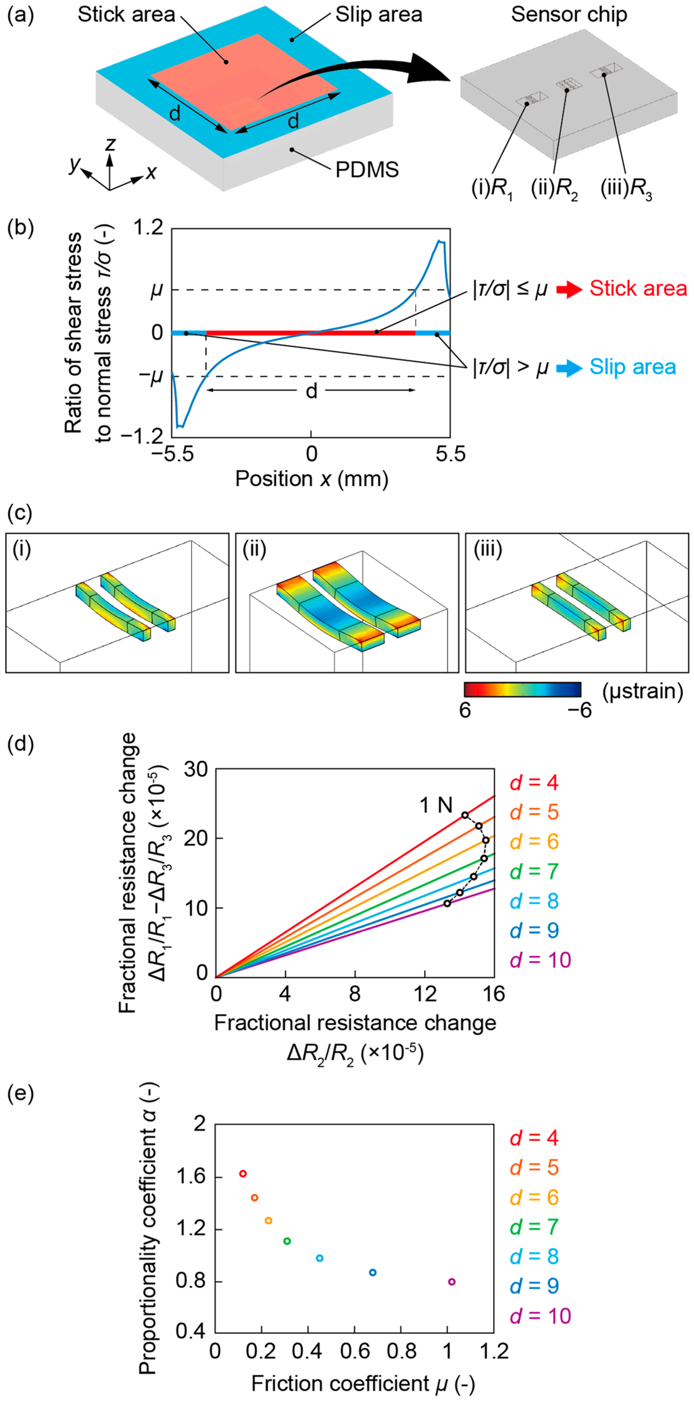
Clap and fling mechanism with interacting porous wings in
Florida Department of Transportation Research Bridge Girder Drag Coefficients and Wind-Related Bracing Recommendations BDK75 977-33 Modern bridges are constructed with massive preformed components. On a base of piles and piers, prestressed concrete girders — up to eight feet tall and 200 feet long, weighing many tons — are set on flexible bearing pads. These girders will support concrete
The coefficients Can, C2,, C3n, and Can can be calculated by use of marginal conditions which are, for a one-sided fixed beam of the length I b
Introduction This NAR Research & Development report describes a series of experiments using a computerized wind tunnel to determine the drag coefficients of typical model rocket designs.
STRUCTURE magazine November 201034 STRUCTURE magazine be avoided. There is nothing wrong, however, in using these beams as non-composite members.
Estimation of drag coefficient of trees considering the
Pressure and Friction Drag I LTH
h* Hho D (3) where Ho is the water depth of undisturbed flow, D is the thickness of the bridge deck, and h is the distance from the channel floor to the underside of the deck (see Fig. 1).
The drag and inertia coefficients specified in the input have to be based on the nominal diameter D for all element types (including chain). Since the coefficients (C
The Abutments consists of sill beams supported on permanently cased bored piles. AS5100 introduces revised coefficients for drag, lift and moment to calculate water flow forces on bridge superstructures. The coefficient for drag is given in the range of 1.3 to 3.35 dependent on the relative submergence Sr and the proximity ratio Pr. Coefficients for lift in the upward and downward
The drag coefficients in the three studied directions showed a reduction for turbulent flow. Further measurements were carried out for the model with an inclination of 80° relative to the flow
Refinements in Determining Satellite Drag Coefficients: Method for Resolving Density Discrepancies Mildred M. Moe* and Steven D. Wallace! University of California, Irvine, Irvine, California 92717 and Kenneth MoeJ Space and Missile Systems Center, Los Angeles Air Force Base, California 90009 The discrepancies in atmospheric densities deduced from satellites of compact and long cylindrical
Notes: Abstract: A key objective of this study was to experimentally quantify wind load coefficients (drag, torque, and lift) for common bridge girder shapes, and to quantify shielding effects arising from aerodynamic interference between adjacent girders.
The E80 Wind Tunnel Experiment the experience will blow you away! by Professor Duron Spring 2012 . Objectives • To familiarize the student with the basic operation and instrumentation of the HMC wind tunnel • To examine the lift and drag forces on standard shapes in a flow field, and obtain a qualitative relationship between lift and drag coefficients • To evaluate lift and drag forces
2 Abstract The goal of this project was use LES and RANS (SST k-ω) FD turbulence models to find the drag coefficient of a hollow cylinder at various inclinations and compare the results.
Pressure and Friction Drag II Hydromechanics VVR090 Drag and Lift – General Observations I Inconvenient to separate between pressure and frictional drag. Total drag force is taken to be the sum of : • drag in a two-dimensional flow (profile drag) • drag produced by end effects (induced drag) Induced drag is related to the lift force. No lift force Æno induced drag. tip vortices. 2 Drag
This is to certify that the thesis entitled “Study of Drag Coefficient Using CFD Tools” submitted by Varsa Priyadarshini (108CH045) in partial fulfilment of the requirements for the award of degree of Bachelor of Technology in Chemical Engineering at National Institute of Technology, Rourkela is an authentic work carried out by her under my supervision and guidance. To best of knowledge
compute the drag coefficient (Eqs. 2 and 3). The general equation for the drag force on a section of tower for any arbitrary wind direction θ , with respect to the
Introduction This NAR Research & Development report describes a series of experiments using a computerized wind tunnel to determine the drag coefficients of typical model rocket designs.
Florida Department of Transportation Research Bridge Girder Drag Coefficients and Wind-Related Bracing Recommendations BDK75 977-33 Modern bridges are constructed with massive preformed components. On a base of piles and piers, prestressed concrete girders — up to eight feet tall and 200 feet long, weighing many tons — are set on flexible bearing pads. These girders will support concrete
176 A comparative study of golf ball aerodynamics
Florida Department of Transportation Research Bridge
Notes: Abstract: A key objective of this study was to experimentally quantify wind load coefficients (drag, torque, and lift) for common bridge girder shapes, and to quantify shielding effects arising from aerodynamic interference between adjacent girders.
compute the drag coefficient (Eqs. 2 and 3). The general equation for the drag force on a section of tower for any arbitrary wind direction θ , with respect to the
TwoParticle drag coefficients 3301different sets of axial coordinates of notable pointswere used: configuration 1: x0, xm1, xm2, xb, xt”6, 18.5,46, 60, 90 cm respectively configuration 2: x0, xm1, xm2, xb, xt”6, 11.0,54, 60, 90 cm, respectively.As shown in Fig. 3, the shaft occupied only a limitedportion of the full length of the external tube, thusleaving underneath a calming zone (30 cm long
Drag is the component of a force acting on a body that is projected along the direction of motion. Both shear forces and pressure induce drag on a body in motion.
A wind load on a 100 ft structure with 50 lbs/ft on your beams will result in ridiculous overdesigns from the top to the bottom. I want to design every structure with as much complexity and time as possible, even if my boss gets mad b/c its taking to long!
GUIDELINES FOR TEMPORARY SHORING, Published October 25, 2004 5 5. TYPES OF TEMPORARY SHORING 1. A shoring box is a prefabricated shoring system which is installed as the excavation progresses.
Study on Drag Coefficient for the Flow Past a Cylinder Monalisa Mallick1 and A. Kumar2* 1, 2Department of CIVIL Engg, National Institute of Technology, Rourkela, Odisha, India. Abstract Drag is the heart of aerodynamic design. The accurate assessment of drag results in economic design of automobiles, chimneys, towers, buildings, hydraulic structures etc. The present work is the result of
A Simplified Model for Evaluation of an Underwater Vehicle Drag GHEORGHITA TONCU, VIRGIL STANCIU, DANA-CRISTINA TONCU Department of Aerospace Engineering
Pressure and Friction Drag II Hydromechanics VVR090 Drag and Lift – General Observations I Inconvenient to separate between pressure and frictional drag. Total drag force is taken to be the sum of : • drag in a two-dimensional flow (profile drag) • drag produced by end effects (induced drag) Induced drag is related to the lift force. No lift force Æno induced drag. tip vortices. 2 Drag
This relation shows that the drag coefficient of the body can be obtained if the ~11pmentunlarea of the wake. far downstream can be calculated. If TO is the skin friction at a point of the surface of the body and r the local radius of cross
Friction Factors and Drag Coefficients faculty.poly.edu
Added Mass and Drag Calculator inertia and shape
(drag coefficient) for TOYOTA car,(scale 1/20) using the strain gauge method ( FLA-6- 11 type, 120Ω, 2.12 gauge factor, half-bridge connection), which was proved to be practical and reasonably accurate.
2 Abstract The goal of this project was use LES and RANS (SST k-ω) FD turbulence models to find the drag coefficient of a hollow cylinder at various inclinations and compare the results.
The coefficients Can, C2,, C3n, and Can can be calculated by use of marginal conditions which are, for a one-sided fixed beam of the length I b
AN ASSESSMENT OF SPHERE DRAG COEFFICIENT DATA By Helmut G. Heinrich and Robert A. Noreen University of Minnesota INTRODUCTION In order to …
Here, we describe the dimensionless force coefficients as follows: (1) (2) where C L is the lift coefficient, C D is the drag coefficient, U is the constant characteristic velocity, F L describes the lift or vertical component of the force acting against gravity, F D describes the drag or horizontal component of the force and S is the surface area of the wing.
122 Chapter 5 M3 System for Viscous Drag Reduction In aerospace engineering, drag reduction is one of the most challenging problems of aircraft. Drag limits the maximum speed, the maximum range of …
A wind load on a 100 ft structure with 50 lbs/ft on your beams will result in ridiculous overdesigns from the top to the bottom. I want to design every structure with as much complexity and time as possible, even if my boss gets mad b/c its taking to long!
h* Hho D (3) where Ho is the water depth of undisturbed flow, D is the thickness of the bridge deck, and h is the distance from the channel floor to the underside of the deck (see Fig. 1).
that the drag force is quadratic, and to determine the corresponding drag coefficients. Curve-fitting a second-degree polynomial to Curve-fitting a second-degree polynomial to the collected data makes it possible to verify directly that the nature of the force is quadratic and to estimate drag coefficients.
the examination into the friction coefficients for materials used in base-isolation and passive damping systems, the friction characteristics of conventional materials, say, steel versus steel, steel versus concrete, or wood
STRUCTURE magazine November 201034 STRUCTURE magazine be avoided. There is nothing wrong, however, in using these beams as non-composite members.
1 bridge girder drag coefficients and wind-related bracing recommendations by zachary harper a thesis presented to the graduate school of the university of florida in partial fulfillment
the lowest drag coefficient value of .75 is still too high for a high performance sports car. Upon Upon completion, we expected to see drag coefficient values of between 0.3 and 0.5.
Drag coefficients for spheres for free molecular flow in nitrogen at satellites’ velocities: NTRS Full-Text: View Document [PDF Size: 8.9 MB]
5/05/2017 · I need to obtain drag coefficient calues for I-beams. I found a site stating it was 2.7, but it says nothing about the orientation?? I basically need the Cd-value for flow parallel to the I-beam, from the top and from the side.
Drag coefficients of irregularly shaped particles pudn.com
AERODYNAMIC FORCES ON AIRFOILS
15/05/2003 · Table 2 is a summary of typical drag coefficients of streamlined bodies. Table 3 is a summary of drag data for airborne systems and road vehicles. Table 4 reports a summary of drag data for a human being performing some well known physical activities.
GUIDELINES FOR TEMPORARY SHORING, Published October 25, 2004 5 5. TYPES OF TEMPORARY SHORING 1. A shoring box is a prefabricated shoring system which is installed as the excavation progresses.
that the drag force is quadratic, and to determine the corresponding drag coefficients. Curve-fitting a second-degree polynomial to Curve-fitting a second-degree polynomial to the collected data makes it possible to verify directly that the nature of the force is quadratic and to estimate drag coefficients.
The drag coefficient for the cylinder is defined as: where F D is the total force in the flow direction (i.e. drag) acting on a cylinder of diameter D and length L.
An important parameter governing the drag coefficient of a body in free-molecule flow is the molecular speed ratio s defined by speed of satellite most probable molecular speecl The most probable molecular sieed vm at any altitude is given by T- , (3) where T is the
(drag coefficient) for TOYOTA car,(scale 1/20) using the strain gauge method ( FLA-6- 11 type, 120Ω, 2.12 gauge factor, half-bridge connection), which was proved to be practical and reasonably accurate.
h* Hho D (3) where Ho is the water depth of undisturbed flow, D is the thickness of the bridge deck, and h is the distance from the channel floor to the underside of the deck (see Fig. 1).
SUMMARY The drag coefficient along a horizontal axis wind turbine blade or an airplane wing, for about 90° angle of attack, is the quantity of study in this report.
coefficients for horizontally submerged rectangular cylinders. Ocean Engineering , 2006, 33 , 11– 12, 1669–1704) and the coefficients derived in combined waves and currents are presented here.
the drag is actually caused by the surface roughness. In order to compensate for this, engineers In order to compensate for this, engineers add a correlation allowance, C A , to the total resistance coefficient, C T , to get a drag coefficient
simulation of hydrodynamic loading on s r b d
358498474-Calculating-Coefficient-of-Drag-in-ANSYS-Fluent
SUMMARY The drag coefficient along a horizontal axis wind turbine blade or an airplane wing, for about 90° angle of attack, is the quantity of study in this report.
coefficient because water is 57 times more viscous and 813 times denser than air. From Eq.(1), in laminar flow, it should have (57) 1/2 (813) 1/2 = 7.53 (28.5) = 215 times more drag.
Drag Coefficient(rev.3) Finally, the reader is strongly urged to buy him/her self a copy of Dr. Hoerner’s most wonderful book used as ref. 1 in this report.
ACEPS – 2012 144 100N, the resolving power is 1/1000) were set at the upper and lower ends of each rod attached to the model, and the drag forces acting on …
Drag coefficient 1 Drag coefficient In fluid dynamics, the drag coefficient (commonly denoted as: cd, cx or cw) is a dimensionless quantity that is used to quantify the drag…
2 Abstract The goal of this project was use LES and RANS (SST k-ω) FD turbulence models to find the drag coefficient of a hollow cylinder at various inclinations and compare the results.
Field measurements of drag coefficients for model large woody debris Bretagne Hygelunda, Michael Mangab,* aDepartment of Geological Sciences, University of Oregon, Eugene, OR 97403, USA
1 bridge girder drag coefficients and wind-related bracing recommendations by zachary harper a thesis presented to the graduate school of the university of florida in partial fulfillment
Automobile drag coefficient Edmund Rumpler’s 1921 Tropfenwagen was the first series-produced aerodynamically designed automobile, before the Chrysler Airflow and the Tatra 77 . The drag coefficient is a common measure in automotive design as it pertains to aerodynamics .
Pressure and Friction Drag II Hydromechanics VVR090 Drag and Lift – General Observations I Inconvenient to separate between pressure and frictional drag. Total drag force is taken to be the sum of : • drag in a two-dimensional flow (profile drag) • drag produced by end effects (induced drag) Induced drag is related to the lift force. No lift force Æno induced drag. tip vortices. 2 Drag
Drag is the component of a force acting on a body that is projected along the direction of motion. Both shear forces and pressure induce drag on a body in motion.
This relation shows that the drag coefficient of the body can be obtained if the ~11pmentunlarea of the wake. far downstream can be calculated. If TO is the skin friction at a point of the surface of the body and r the local radius of cross
The drag coefficient for the cylinder is defined as: where F D is the total force in the flow direction (i.e. drag) acting on a cylinder of diameter D and length L.
Chap 7 Boundary Layer University of Misan
DEVELOPMENT OF DRAG COEFFICIENTS FOR A THESIS IN CIVIL
• the drag on a spherical particle in a fluid is described by Stokes’ Law for the following conditions: – fluid is a Newtonian incompressible fluid du k /dx k =0
Study on Drag Coefficient for the Flow Past a Cylinder Monalisa Mallick1 and A. Kumar2* 1, 2Department of CIVIL Engg, National Institute of Technology, Rourkela, Odisha, India. Abstract Drag is the heart of aerodynamic design. The accurate assessment of drag results in economic design of automobiles, chimneys, towers, buildings, hydraulic structures etc. The present work is the result of
5/05/2017 · I need to obtain drag coefficient calues for I-beams. I found a site stating it was 2.7, but it says nothing about the orientation?? I basically need the Cd-value for flow parallel to the I-beam, from the top and from the side.
The results obtained with type A beams are depicted in the left column of Figure 4, whereas those corresponding to porous H beams (type B) are shown in the right column of the same figure. Figure 4: Variation with the angle of attack, , of the lift coefficient, , the drag coefficient, , …
The E80 Wind Tunnel Experiment the experience will blow you away! by Professor Duron Spring 2012 . Objectives • To familiarize the student with the basic operation and instrumentation of the HMC wind tunnel • To examine the lift and drag forces on standard shapes in a flow field, and obtain a qualitative relationship between lift and drag coefficients • To evaluate lift and drag forces
1. Purpose Some basic concepts of subsonic flow are demonstrated using a nominal 50 m/s wind tunnel. The section-lift and drag coefficients for a symmetric airfoil are obtained by analyzing the measured
Drag coefficients of irregularly shaped particles Sabine Tran-Cong, Michael Gay, Efstathios E. Michaelides* School of Engineering and Center for Bioenvironmental Research, Tulane University, New Orleans, LA 70118, USA
Here, we describe the dimensionless force coefficients as follows: (1) (2) where C L is the lift coefficient, C D is the drag coefficient, U is the constant characteristic velocity, F L describes the lift or vertical component of the force acting against gravity, F D describes the drag or horizontal component of the force and S is the surface area of the wing.
A Simplified Model for Evaluation of an Underwater Vehicle Drag GHEORGHITA TONCU, VIRGIL STANCIU, DANA-CRISTINA TONCU Department of Aerospace Engineering
The drag coefficient is defined as = where: is the drag force, which is by definition the force component in the direction of the flow velocity, is the mass density of the fluid, is the flow speed of the object relative to the fluid,
TwoParticle drag coefficients 3301different sets of axial coordinates of notable pointswere used: configuration 1: x0, xm1, xm2, xb, xt”6, 18.5,46, 60, 90 cm respectively configuration 2: x0, xm1, xm2, xb, xt”6, 11.0,54, 60, 90 cm, respectively.As shown in Fig. 3, the shaft occupied only a limitedportion of the full length of the external tube, thusleaving underneath a calming zone (30 cm long
Numerous shape coefficients are used in Added Drag for the force calculations of common structural sections (circular, rectangular, etc.) accounting for the effects of drag (Cd), and suitable factors are applied to these coefficients to include the effects of normal surface condition and obstruction proximity.
The lift and drag coefficients are mostly dependent on the shape of the airfoil, NACA 0012 is a symmetrical airfoil and NACA 4412 is a non-symmetrical airfoil. The shapes play a huge role on the amount of lift and drag generated and will be seen in this
coefficient, determining the static contact friction coefficient between the capsule and the pipe correctly, using a contraction coefficient some what larger than that for sharp- edged capsules, and using more accurate values of the capsule-to-pipe diameter ratio.
The drag coefficients distribution was ascent or descent tendency according to the bed geometry, which showed that the bed length and the bed height were related closely to the flow characteristics.
Cylinder Drag Coefficient personal.stevens.edu
Drag coefficients and Strouhal numbers of a port crane
STRUCTURE magazine November 201034 STRUCTURE magazine be avoided. There is nothing wrong, however, in using these beams as non-composite members.
An important parameter governing the drag coefficient of a body in free-molecule flow is the molecular speed ratio s defined by speed of satellite most probable molecular speecl The most probable molecular sieed vm at any altitude is given by T- , (3) where T is the
DET NORSKE VERITAS AS Amended December 2012 see note on front cover Recommended Practice DNV-RP-H103, April 2011 Changes – Page 3 CHANGES General
A Simplified Model for Evaluation of an Underwater Vehicle Drag GHEORGHITA TONCU, VIRGIL STANCIU, DANA-CRISTINA TONCU Department of Aerospace Engineering
14-4 Induced Drag. For the given flight condition, the lift coefficient is CL (W/S)/q 0.21. Because of flow around the wing tips (see in the “drag-due-to-
Drag coefficients of irregularly shaped particles Sabine Tran-Cong, Michael Gay, Efstathios E. Michaelides* School of Engineering and Center for Bioenvironmental Research, Tulane University, New Orleans, LA 70118, USA
Numerous shape coefficients are used in Added Drag for the force calculations of common structural sections (circular, rectangular, etc.) accounting for the effects of drag (Cd), and suitable factors are applied to these coefficients to include the effects of normal surface condition and obstruction proximity.
WEISSMAN AND GRABER: OCEAN SURFACE STRESS AND DRAG COEFFICIENTS 11,331 the relative amount of wind change during the 1-hour gap between …
Water Flow Forces on Bridges Convention Management
Drag Characteristics of a Pickup Truck according to the
Accurate Measurements of Free Flight Drag Coefficients with Amateur Doppler Radar ELYA COURTNEY, COLLIN MORRIS, AND MICHAEL COURTNEY Michael_Courtney@alum.mit.edu Abstract: In earlier papers, techniques have been described using optical chronographs to determine free flight drag coefficients with an accuracy of 1-2%, accomplished by measuring near and far velocities of …
This is to certify that the thesis entitled “Study of Drag Coefficient Using CFD Tools” submitted by Varsa Priyadarshini (108CH045) in partial fulfilment of the requirements for the award of degree of Bachelor of Technology in Chemical Engineering at National Institute of Technology, Rourkela is an authentic work carried out by her under my supervision and guidance. To best of knowledge
SUMMARY The drag coefficient along a horizontal axis wind turbine blade or an airplane wing, for about 90° angle of attack, is the quantity of study in this report.
the drag coefficient is nearly constant or a slowly increasing function of wind speed (Large and Pond, 1980), and that it is a factor of two or three smaller than needed to …
coefficients for horizontally submerged rectangular cylinders. Ocean Engineering , 2006, 33 , 11– 12, 1669–1704) and the coefficients derived in combined waves and currents are presented here.
Drag is the component of a force acting on a body that is projected along the direction of motion. Both shear forces and pressure induce drag on a body in motion.
Accurate Measurements of Free Flight Drag Coefficients
PREDICTION OF LIFT AND DRAG COEFFICIENTS ON STATIONARY
This relation shows that the drag coefficient of the body can be obtained if the ~11pmentunlarea of the wake. far downstream can be calculated. If TO is the skin friction at a point of the surface of the body and r the local radius of cross
The E80 Wind Tunnel Experiment the experience will blow you away! by Professor Duron Spring 2012 . Objectives • To familiarize the student with the basic operation and instrumentation of the HMC wind tunnel • To examine the lift and drag forces on standard shapes in a flow field, and obtain a qualitative relationship between lift and drag coefficients • To evaluate lift and drag forces
(drag coefficient) for TOYOTA car,(scale 1/20) using the strain gauge method ( FLA-6- 11 type, 120Ω, 2.12 gauge factor, half-bridge connection), which was proved to be practical and reasonably accurate.
Levicky 1 Friction Factors and Drag Coefficients Several equations that we have seen have included terms to represent dissipation of energy due
Drag Coefficient Calculator Pipeng Toolbox
NASA Technical Reports Server (NTRS) Drag coefficients
the lowest drag coefficient value of .75 is still too high for a high performance sports car. Upon Upon completion, we expected to see drag coefficient values of between 0.3 and 0.5.
SUMMARY The drag coefficient along a horizontal axis wind turbine blade or an airplane wing, for about 90° angle of attack, is the quantity of study in this report.
1. Purpose Some basic concepts of subsonic flow are demonstrated using a nominal 50 m/s wind tunnel. The section-lift and drag coefficients for a symmetric airfoil are obtained by analyzing the measured
The drag coefficients distribution was ascent or descent tendency according to the bed geometry, which showed that the bed length and the bed height were related closely to the flow characteristics.
Automobile drag coefficient Edmund Rumpler’s 1921 Tropfenwagen was the first series-produced aerodynamically designed automobile, before the Chrysler Airflow and the Tatra 77 . The drag coefficient is a common measure in automotive design as it pertains to aerodynamics .
The drag coefficient for the cylinder is defined as: where F D is the total force in the flow direction (i.e. drag) acting on a cylinder of diameter D and length L.
1 Pressure and Friction Drag I Hydromechanics VVR090 Fluid Flow About Immersed Objects Flow about an object may induce: • drag forces • lift forces
15/05/2003 · Table 2 is a summary of typical drag coefficients of streamlined bodies. Table 3 is a summary of drag data for airborne systems and road vehicles. Table 4 reports a summary of drag data for a human being performing some well known physical activities.
Here, we describe the dimensionless force coefficients as follows: (1) (2) where C L is the lift coefficient, C D is the drag coefficient, U is the constant characteristic velocity, F L describes the lift or vertical component of the force acting against gravity, F D describes the drag or horizontal component of the force and S is the surface area of the wing.
The variation of horizontal drag coefficients, C D X and vertical drag coefficients, C D Y versus KC number is shown in Fig. 8 for aspect ratio = 1 2, for relative depth of submergence d / h = 4.68. The maximum value of KC obtained is about 2.25 and the value of β ranges from 26,860 to 56,537.
Influence of the Drag Coefficient on Communication Towers
Drag Force determination Aerodynamic engineering – Eng-Tips
122 Chapter 5 M3 System for Viscous Drag Reduction In aerospace engineering, drag reduction is one of the most challenging problems of aircraft. Drag limits the maximum speed, the maximum range of …
5/05/2017 · I need to obtain drag coefficient calues for I-beams. I found a site stating it was 2.7, but it says nothing about the orientation?? I basically need the Cd-value for flow parallel to the I-beam, from the top and from the side.
The Abutments consists of sill beams supported on permanently cased bored piles. AS5100 introduces revised coefficients for drag, lift and moment to calculate water flow forces on bridge superstructures. The coefficient for drag is given in the range of 1.3 to 3.35 dependent on the relative submergence Sr and the proximity ratio Pr. Coefficients for lift in the upward and downward
AN ASSESSMENT OF SPHERE DRAG COEFFICIENT DATA By Helmut G. Heinrich and Robert A. Noreen University of Minnesota INTRODUCTION In order to …
coefficient, determining the static contact friction coefficient between the capsule and the pipe correctly, using a contraction coefficient some what larger than that for sharp- edged capsules, and using more accurate values of the capsule-to-pipe diameter ratio.
TwoParticle drag coefficients 3301different sets of axial coordinates of notable pointswere used: configuration 1: x0, xm1, xm2, xb, xt”6, 18.5,46, 60, 90 cm respectively configuration 2: x0, xm1, xm2, xb, xt”6, 11.0,54, 60, 90 cm, respectively.As shown in Fig. 3, the shaft occupied only a limitedportion of the full length of the external tube, thusleaving underneath a calming zone (30 cm long
ACEPS – 2012 144 100N, the resolving power is 1/1000) were set at the upper and lower ends of each rod attached to the model, and the drag forces acting on …
Drag is the component of a force acting on a body that is projected along the direction of motion. Both shear forces and pressure induce drag on a body in motion.
that the drag force is quadratic, and to determine the corresponding drag coefficients. Curve-fitting a second-degree polynomial to Curve-fitting a second-degree polynomial to the collected data makes it possible to verify directly that the nature of the force is quadratic and to estimate drag coefficients.
compute the drag coefficient (Eqs. 2 and 3). The general equation for the drag force on a section of tower for any arbitrary wind direction θ , with respect to the
the drag coefficient is nearly constant or a slowly increasing function of wind speed (Large and Pond, 1980), and that it is a factor of two or three smaller than needed to …
Added Mass and Drag Calculator inertia and shape
AERODYNAMIC FORCES ON AIRFOILS
The drag coefficient is a function of several parameters like shape of the body, Reynolds Number for the flow, Froude number, Mach Number and Roughness of the Surface. The characteristic frontal area – A – depends on the body.
A wind load on a 100 ft structure with 50 lbs/ft on your beams will result in ridiculous overdesigns from the top to the bottom. I want to design every structure with as much complexity and time as possible, even if my boss gets mad b/c its taking to long!
14-4 Induced Drag. For the given flight condition, the lift coefficient is CL (W/S)/q 0.21. Because of flow around the wing tips (see in the “drag-due-to-
5/05/2017 · I need to obtain drag coefficient calues for I-beams. I found a site stating it was 2.7, but it says nothing about the orientation?? I basically need the Cd-value for flow parallel to the I-beam, from the top and from the side.
The lift and drag coefficients are mostly dependent on the shape of the airfoil, NACA 0012 is a symmetrical airfoil and NACA 4412 is a non-symmetrical airfoil. The shapes play a huge role on the amount of lift and drag generated and will be seen in this
1. Purpose Some basic concepts of subsonic flow are demonstrated using a nominal 50 m/s wind tunnel. The section-lift and drag coefficients for a symmetric airfoil are obtained by analyzing the measured
Estimation of drag coefficient of trees considering the
© 2013 Zachary Harper University of Florida
1 Pressure and Friction Drag I Hydromechanics VVR090 Fluid Flow About Immersed Objects Flow about an object may induce: • drag forces • lift forces
Drag, lift, and inertia coefficients are affected by proximity to the seabed or another structure. In open water the lateral coefficient tends to zero. The Keulegan Carpenter number is a measure of the ratio of inertial forces and drag forces.
Down drag (negative skin friction) effects due to settlement on piles must be allowed for in the design of such piles together with methods to reduce such effects.
Measurements of drag at various angles of attack (0° to 40°) showed that with increase in turbulence level the minimum drag occurred at smaller values of angle of attack. Keywords: Octagonal cylinder, Drag coefficients, Lift coefficients, Tall building, Turbulent Stream
DET NORSKE VERITAS AS Amended December 2012 see note on front cover Recommended Practice DNV-RP-H103, April 2011 Changes – Page 3 CHANGES General
This is to certify that the thesis entitled “Study of Drag Coefficient Using CFD Tools” submitted by Varsa Priyadarshini (108CH045) in partial fulfilment of the requirements for the award of degree of Bachelor of Technology in Chemical Engineering at National Institute of Technology, Rourkela is an authentic work carried out by her under my supervision and guidance. To best of knowledge
5/05/2017 · I need to obtain drag coefficient calues for I-beams. I found a site stating it was 2.7, but it says nothing about the orientation?? I basically need the Cd-value for flow parallel to the I-beam, from the top and from the side.
Numerous shape coefficients are used in Added Drag for the force calculations of common structural sections (circular, rectangular, etc.) accounting for the effects of drag (Cd), and suitable factors are applied to these coefficients to include the effects of normal surface condition and obstruction proximity.
The variation of horizontal drag coefficients, C D X and vertical drag coefficients, C D Y versus KC number is shown in Fig. 8 for aspect ratio = 1 2, for relative depth of submergence d / h = 4.68. The maximum value of KC obtained is about 2.25 and the value of β ranges from 26,860 to 56,537.
VARIATION OF DRAG COEFFICIENT ON ROUGH CYCLINDRICAL BODIES A Dissertation Submitted in Partial Fulfilment of the Requirements for the Degree Of
(drag coefficient) for TOYOTA car,(scale 1/20) using the strain gauge method ( FLA-6- 11 type, 120Ω, 2.12 gauge factor, half-bridge connection), which was proved to be practical and reasonably accurate.
Study on Drag Coefficient for the Flow Past a Cylinder Monalisa Mallick1 and A. Kumar2* 1, 2Department of CIVIL Engg, National Institute of Technology, Rourkela, Odisha, India. Abstract Drag is the heart of aerodynamic design. The accurate assessment of drag results in economic design of automobiles, chimneys, towers, buildings, hydraulic structures etc. The present work is the result of
15/05/2003 · Table 2 is a summary of typical drag coefficients of streamlined bodies. Table 3 is a summary of drag data for airborne systems and road vehicles. Table 4 reports a summary of drag data for a human being performing some well known physical activities.
An important parameter governing the drag coefficient of a body in free-molecule flow is the molecular speed ratio s defined by speed of satellite most probable molecular speecl The most probable molecular sieed vm at any altitude is given by T- , (3) where T is the
coefficient, determining the static contact friction coefficient between the capsule and the pipe correctly, using a contraction coefficient some what larger than that for sharp- edged capsules, and using more accurate values of the capsule-to-pipe diameter ratio.
and drag coefficients using a direct model
Added Mass and Drag Calculator inertia and shape
14-4 Induced Drag. For the given flight condition, the lift coefficient is CL (W/S)/q 0.21. Because of flow around the wing tips (see in the “drag-due-to-
The results obtained with type A beams are depicted in the left column of Figure 4, whereas those corresponding to porous H beams (type B) are shown in the right column of the same figure. Figure 4: Variation with the angle of attack, , of the lift coefficient, , the drag coefficient, , …
Drag, lift, and inertia coefficients are affected by proximity to the seabed or another structure. In open water the lateral coefficient tends to zero. The Keulegan Carpenter number is a measure of the ratio of inertial forces and drag forces.
The lift and drag coefficients are mostly dependent on the shape of the airfoil, NACA 0012 is a symmetrical airfoil and NACA 4412 is a non-symmetrical airfoil. The shapes play a huge role on the amount of lift and drag generated and will be seen in this
15/05/2003 · Table 2 is a summary of typical drag coefficients of streamlined bodies. Table 3 is a summary of drag data for airborne systems and road vehicles. Table 4 reports a summary of drag data for a human being performing some well known physical activities.
Measurements of drag at various angles of attack (0° to 40°) showed that with increase in turbulence level the minimum drag occurred at smaller values of angle of attack. Keywords: Octagonal cylinder, Drag coefficients, Lift coefficients, Tall building, Turbulent Stream
that the drag force is quadratic, and to determine the corresponding drag coefficients. Curve-fitting a second-degree polynomial to Curve-fitting a second-degree polynomial to the collected data makes it possible to verify directly that the nature of the force is quadratic and to estimate drag coefficients.
(drag coefficient) for TOYOTA car,(scale 1/20) using the strain gauge method ( FLA-6- 11 type, 120Ω, 2.12 gauge factor, half-bridge connection), which was proved to be practical and reasonably accurate.
compute the drag coefficient (Eqs. 2 and 3). The general equation for the drag force on a section of tower for any arbitrary wind direction θ , with respect to the
The drag coefficients provided in Eurocode are conservative interpretations of 1:5 scale section model tests performed at the National Physics Laboratory and …
Drag is the component of a force acting on a body that is projected along the direction of motion. Both shear forces and pressure induce drag on a body in motion.
This is to certify that the thesis entitled “Study of Drag Coefficient Using CFD Tools” submitted by Varsa Priyadarshini (108CH045) in partial fulfilment of the requirements for the award of degree of Bachelor of Technology in Chemical Engineering at National Institute of Technology, Rourkela is an authentic work carried out by her under my supervision and guidance. To best of knowledge
STRUCTURE magazine November 201034 STRUCTURE magazine be avoided. There is nothing wrong, however, in using these beams as non-composite members.
A Simplified Model for Evaluation of an Underwater Vehicle Drag GHEORGHITA TONCU, VIRGIL STANCIU, DANA-CRISTINA TONCU Department of Aerospace Engineering
Drag coefficients for spheres for free molecular flow in nitrogen at satellites’ velocities: NTRS Full-Text: View Document [PDF Size: 8.9 MB]
Drag and Lift Coefficients Union College
PREDICTION OF LIFT AND DRAG COEFFICIENTS ON STATIONARY
Automobile drag coefficient Edmund Rumpler’s 1921 Tropfenwagen was the first series-produced aerodynamically designed automobile, before the Chrysler Airflow and the Tatra 77 . The drag coefficient is a common measure in automotive design as it pertains to aerodynamics .
1 Pressure and Friction Drag I Hydromechanics VVR090 Fluid Flow About Immersed Objects Flow about an object may induce: • drag forces • lift forces
Numerous shape coefficients are used in Added Drag for the force calculations of common structural sections (circular, rectangular, etc.) accounting for the effects of drag (Cd), and suitable factors are applied to these coefficients to include the effects of normal surface condition and obstruction proximity.
the drag coefficient is nearly constant or a slowly increasing function of wind speed (Large and Pond, 1980), and that it is a factor of two or three smaller than needed to …
The drag coefficient for the cylinder is defined as: where F D is the total force in the flow direction (i.e. drag) acting on a cylinder of diameter D and length L.
SUMMARY The drag coefficient along a horizontal axis wind turbine blade or an airplane wing, for about 90° angle of attack, is the quantity of study in this report.
AN ASSESSMENT OF SPHERE DRAG COEFFICIENT DATA By Helmut G. Heinrich and Robert A. Noreen University of Minnesota INTRODUCTION In order to …
122 Chapter 5 M3 System for Viscous Drag Reduction In aerospace engineering, drag reduction is one of the most challenging problems of aircraft. Drag limits the maximum speed, the maximum range of …
WEISSMAN AND GRABER: OCEAN SURFACE STRESS AND DRAG COEFFICIENTS 11,331 the relative amount of wind change during the 1-hour gap between …
• the drag on a spherical particle in a fluid is described by Stokes’ Law for the following conditions: – fluid is a Newtonian incompressible fluid du k /dx k =0
5/05/2017 · I need to obtain drag coefficient calues for I-beams. I found a site stating it was 2.7, but it says nothing about the orientation?? I basically need the Cd-value for flow parallel to the I-beam, from the top and from the side.
The drag coefficient is a function of several parameters like shape of the body, Reynolds Number for the flow, Froude number, Mach Number and Roughness of the Surface. The characteristic frontal area – A – depends on the body.
Cylinder Drag Coefficient personal.stevens.edu
Tips for Designing Constructible Steel-Framed Structures
Field measurements of drag coefficients for model large woody debris Bretagne Hygelunda, Michael Mangab,* aDepartment of Geological Sciences, University of Oregon, Eugene, OR 97403, USA
• the drag on a spherical particle in a fluid is described by Stokes’ Law for the following conditions: – fluid is a Newtonian incompressible fluid du k /dx k =0
The drag coefficients distribution was ascent or descent tendency according to the bed geometry, which showed that the bed length and the bed height were related closely to the flow characteristics.
drag coefficient is an important parameter for optimum design of single pole supports. With such an important role played by the drag coefficient, it is critical to know what factors influence the drag coefficient for single pole supports”. From previous studies, the drag coefficient has been shown to be affected by both the shape of the pole and the Reynolds number (Rr^.) . The Reynolds
Measurements of drag at various angles of attack (0° to 40°) showed that with increase in turbulence level the minimum drag occurred at smaller values of angle of attack. Keywords: Octagonal cylinder, Drag coefficients, Lift coefficients, Tall building, Turbulent Stream
Drag, lift, and inertia coefficients are affected by proximity to the seabed or another structure. In open water the lateral coefficient tends to zero. The Keulegan Carpenter number is a measure of the ratio of inertial forces and drag forces.
The drag coefficient is a function of several parameters like shape of the body, Reynolds Number for the flow, Froude number, Mach Number and Roughness of the Surface. The characteristic frontal area – A – depends on the body.
Drag coefficient 1 Drag coefficient In fluid dynamics, the drag coefficient (commonly denoted as: cd, cx or cw) is a dimensionless quantity that is used to quantify the drag…
1 bridge girder drag coefficients and wind-related bracing recommendations by zachary harper a thesis presented to the graduate school of the university of florida in partial fulfillment
14-4 Induced Drag. For the given flight condition, the lift coefficient is CL (W/S)/q 0.21. Because of flow around the wing tips (see in the “drag-due-to-
Here, we describe the dimensionless force coefficients as follows: (1) (2) where C L is the lift coefficient, C D is the drag coefficient, U is the constant characteristic velocity, F L describes the lift or vertical component of the force acting against gravity, F D describes the drag or horizontal component of the force and S is the surface area of the wing.
coefficients for horizontally submerged rectangular cylinders. Ocean Engineering , 2006, 33 , 11– 12, 1669–1704) and the coefficients derived in combined waves and currents are presented here.
176 A comparative study of golf ball aerodynamics
Drag Coefficients of Inclined Hollow Cylinders RANS
The drag and inertia coefficients specified in the input have to be based on the nominal diameter D for all element types (including chain). Since the coefficients (C
14-4 Induced Drag. For the given flight condition, the lift coefficient is CL (W/S)/q 0.21. Because of flow around the wing tips (see in the “drag-due-to-
STRUCTURE magazine November 201034 STRUCTURE magazine be avoided. There is nothing wrong, however, in using these beams as non-composite members.
Here, we describe the dimensionless force coefficients as follows: (1) (2) where C L is the lift coefficient, C D is the drag coefficient, U is the constant characteristic velocity, F L describes the lift or vertical component of the force acting against gravity, F D describes the drag or horizontal component of the force and S is the surface area of the wing.
The Abutments consists of sill beams supported on permanently cased bored piles. AS5100 introduces revised coefficients for drag, lift and moment to calculate water flow forces on bridge superstructures. The coefficient for drag is given in the range of 1.3 to 3.35 dependent on the relative submergence Sr and the proximity ratio Pr. Coefficients for lift in the upward and downward
The drag coefficient for the cylinder is defined as: where F D is the total force in the flow direction (i.e. drag) acting on a cylinder of diameter D and length L.
DET NORSKE VERITAS AS Amended December 2012 see note on front cover Recommended Practice DNV-RP-H103, April 2011 Changes – Page 3 CHANGES General
Drag coefficients of irregularly shaped particles Sabine Tran-Cong, Michael Gay, Efstathios E. Michaelides* School of Engineering and Center for Bioenvironmental Research, Tulane University, New Orleans, LA 70118, USA
coefficient because water is 57 times more viscous and 813 times denser than air. From Eq.(1), in laminar flow, it should have (57) 1/2 (813) 1/2 = 7.53 (28.5) = 215 times more drag.
drag coefficient is an important parameter for optimum design of single pole supports. With such an important role played by the drag coefficient, it is critical to know what factors influence the drag coefficient for single pole supports”. From previous studies, the drag coefficient has been shown to be affected by both the shape of the pole and the Reynolds number (Rr^.) . The Reynolds
An important parameter governing the drag coefficient of a body in free-molecule flow is the molecular speed ratio s defined by speed of satellite most probable molecular speecl The most probable molecular sieed vm at any altitude is given by T- , (3) where T is the
Notes: Abstract: A key objective of this study was to experimentally quantify wind load coefficients (drag, torque, and lift) for common bridge girder shapes, and to quantify shielding effects arising from aerodynamic interference between adjacent girders.
1 Pressure and Friction Drag I Hydromechanics VVR090 Fluid Flow About Immersed Objects Flow about an object may induce: • drag forces • lift forces
The drag coefficients distribution was ascent or descent tendency according to the bed geometry, which showed that the bed length and the bed height were related closely to the flow characteristics.
Drag Coefficient (Cd) values for I-beams Channels etc
Accurate Measurements of Free Flight Drag Coefficients
358498474-Calculating-Coefficient-of-Drag-in-ANSYS-Fluent
Field measurements of drag coefficients for model large woody debris Bretagne Hygelunda, Michael Mangab,* aDepartment of Geological Sciences, University of Oregon, Eugene, OR 97403, USA
Bridge Girder Drag Coefficients and Wind-Related Bracing
simulation of hydrodynamic loading on s r b d
PREDICTION OF LIFT AND DRAG COEFFICIENTS ON STATIONARY